Circuit breaker panel wiring diagrams, often found as PDF documents, are crucial for safe and effective electrical system management. They detail connections,
wire numbering, and abbreviations, aiding in troubleshooting and maintenance. Understanding these diagrams, alongside ANSI/IEEE standards, is paramount for electricians and DIY enthusiasts alike.
Understanding the Importance of Diagrams
Circuit breaker panel wiring diagram PDFs are indispensable for anyone working with electrical systems. They provide a visual roadmap, detailing how each component connects, ensuring safe modifications and repairs. Misinterpreting these diagrams can lead to dangerous situations, including electrical shocks or fires.
These diagrams clarify wire numbering conventions and decode abbreviations used by electricians, streamlining troubleshooting. Understanding ANSI/IEEE standard device numbers, like the Master Element (1) or Time Delay Relay (2), is also vital. A clear diagram allows for efficient identification of miswired circuits or overloaded systems, preventing potential hazards and ensuring the longevity of your electrical infrastructure. Accurate diagrams are, therefore, not just helpful – they are essential for safety and compliance.
Safety Precautions When Working with Electrical Panels
Before referencing a circuit breaker panel wiring diagram PDF and commencing any work, always disconnect the main power supply. Confirm the power is off using a non-contact voltage tester. Treat every wire as live until proven otherwise. Wear appropriate personal protective equipment (PPE), including insulated gloves and safety glasses.
Never work alone; have someone nearby in case of emergency. Thoroughly understand the diagram before making any connections. If unsure about any aspect, consult a qualified electrician. Avoid working in damp or wet conditions. Remember, even with a detailed diagram, electrical work carries inherent risks. Prioritize safety above all else, and adhere to local electrical codes. Ignoring these precautions can result in severe injury or death.

Types of Circuit Breaker Panels
Circuit breaker panel wiring diagram PDFs illustrate variations like main panels, subpanels, and configurations such as ranch styles, including Westinghouse DHP panels, each with unique layouts.
Main Panel vs. Subpanel
Circuit breaker panel wiring diagram PDFs clearly differentiate between main panels and subpanels. The main panel receives power directly from the utility company, distributing electricity throughout the entire building. Diagrams showcase its larger size and higher amperage capacity, often 200A as noted.
Subpanels, conversely, are fed from the main panel, typically using two lugs capable of carrying 200A to a subpanel inside the house, though limited by wire gauge – like 115A capacity with a rounded-up 125A breaker. PDF wiring diagrams illustrate this feeder connection and the subpanel’s localized circuit distribution. Understanding this distinction is vital for tracing circuits and performing safe electrical work.
Ranch Panel Configurations
Circuit breaker panel wiring diagram PDFs often depict “ranch panel” configurations, characterized by their unique design. These panels feature two lugs at the bottom, specifically engineered to deliver full 200A to a subpanel located within the residence. However, practical limitations exist; wire gauge often restricts the usable amperage.
As highlighted in available resources, a common scenario involves using two copper wires rated for 115A, necessitating a conservative approach. While the feeder allows rounding up to a 125A breaker, the wiring dictates the safe operational limit. Diagrams will illustrate these connections, emphasizing the importance of adhering to wire capacity when interpreting the PDF.
Westinghouse DHP Panel Overview
Circuit breaker panel wiring diagram PDFs for Westinghouse DHP panels often showcase complex DC control wiring schemes. These diagrams illustrate the electrical operating sequence of the circuit breaker, detailing components involved in activation and deactivation. A typical wiring layout, as found in associated documentation, utilizes DC control for precise operation.
The black wires are fed through separate circuit breakers, while white wires connect to the mains transformer return (RTN) via a common terminal block. Safety grounds connect to earth ground through another terminal block. Understanding these connections, as depicted in the PDF, is crucial for troubleshooting and maintenance of these systems.
Essential Components of a Circuit Breaker Panel
Circuit breaker panel wiring diagram PDFs clearly illustrate key components: circuit breakers, bus bars for power distribution, grounding/bonding systems, and the neutral bus bar.
Circuit Breakers (Individual Switches)
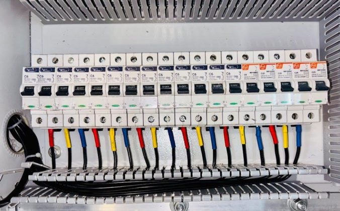
Circuit breaker panel wiring diagram PDFs meticulously detail each individual switch, or circuit breaker, within the panel. These diagrams showcase how breakers connect to the bus bars, illustrating the flow of electricity to specific circuits. The diagrams often indicate amperage ratings for each breaker, crucial for preventing overloads.
Understanding breaker connections, as shown in the PDF, is vital for identifying miswired circuits or recognizing overloaded systems. Diagrams will often use ANSI/IEEE standard device numbers to label breaker functions, like a ‘Master Element’ (1). Correctly interpreting these diagrams ensures safe and efficient electrical system operation, allowing for targeted troubleshooting and repairs.
Bus Bars (Power Distribution)
Circuit breaker panel wiring diagram PDFs clearly illustrate the bus bar system – the central power distribution point. These diagrams depict how the main power feeds into the bus bars, and subsequently, how individual circuit breakers tap into this power source. Understanding this distribution network is key to tracing electrical pathways.
The PDF will show connections for both hot (black) and neutral (white) bus bars, and importantly, the grounding system. Diagrams often detail the physical arrangement of bus bars within the panel. Correctly interpreting these diagrams allows for safe identification of power sources and potential issues, ensuring proper voltage and current flow throughout the electrical system.
Grounding and Bonding Systems
Circuit breaker panel wiring diagram PDFs meticulously detail the grounding and bonding systems, vital for electrical safety. These diagrams illustrate how the panel connects to earth ground, providing a path for fault currents. They showcase the connection points for safety grounds, often via a dedicated terminal block, as indicated in the diagrams.
Understanding these systems, as depicted in the PDF, is crucial for preventing electrical shock and ensuring proper operation of overcurrent protection devices. Diagrams clarify bonding connections between the panel, metallic conduits, and other grounded elements. Correct interpretation ensures a safe and compliant electrical installation, protecting both property and individuals.
Neutral Bus Bar
Circuit breaker panel wiring diagram PDFs clearly illustrate the neutral bus bar’s role in the electrical system. These diagrams show how white neutral wires connect to the mains transformer return (RTN) via a common terminal block, as frequently depicted. The PDF will detail the physical location and connection method for these neutral conductors.
Properly understanding the neutral bus bar’s function, as shown in the diagram, is essential for safe and efficient operation. It provides a return path for current, completing the circuit. Diagrams highlight the importance of secure connections and correct wire sizing. Accurate interpretation of the PDF ensures a stable and reliable electrical system.
Decoding a Circuit Breaker Panel Wiring Diagram PDF
Circuit breaker panel wiring diagram PDFs utilize specific wire numbering conventions and abbreviations; understanding ANSI/IEEE standard device numbers, like Master Elements, is key to interpretation.
Wire Numbering Conventions
Wire numbering within a circuit breaker panel wiring diagram PDF isn’t always standardized, but common practices exist. Diagrams frequently employ numerical designations – 8, 9, and so on – to identify specific wires and their corresponding circuits. These numbers correlate directly to the physical labeling found on the breakers themselves within the panel.
Understanding this correlation is vital for tracing circuits and performing accurate work. The diagrams often link these numbers to the connected loads, allowing technicians to quickly identify what each circuit powers. Consistent documentation and careful attention to these conventions are essential for safe and effective electrical work, preventing miswiring and potential hazards.
Abbreviations Used in Diagrams
Circuit breaker panel wiring diagram PDFs frequently utilize abbreviations to condense information and enhance clarity. Common examples include “RTN” denoting the mains transformer return, representing the neutral connection point. Understanding these shorthand notations is crucial for accurate interpretation. Diagrams may also employ codes relating to specific components or wiring types, streamlining the visual representation of complex systems.
Deciphering these abbreviations requires familiarity with electrical terminology and the specific conventions used by the panel manufacturer. Ignoring these shortcuts can lead to misinterpretation and potentially dangerous errors. A dedicated key or legend within the PDF should define all abbreviations used, ensuring proper comprehension.
ANSI/IEEE Standard Device Numbers
Circuit breaker panel wiring diagram PDFs often incorporate ANSI/IEEE standard device numbers for consistent representation of electrical components. These standardized numbers facilitate clear communication and understanding across different diagrams and manufacturers. For instance, “1” typically represents the Master Element, while “2” denotes a Time Delay Starting or Closing Relay. “3” signifies a Checking or Interlocking Relay, crucial for coordinated protection schemes.
Familiarity with these standard numbers allows for quick identification of device functions within the panel. Understanding these codes, as presented in the PDF, is vital for troubleshooting, maintenance, and ensuring the correct operation of the electrical system. These numbers provide a universal language for electrical professionals.
Master Element (1)
Within a circuit breaker panel wiring diagram PDF, the “Master Element” designated by ANSI/IEEE number “1”, represents the primary control point for the entire system. It’s fundamentally the initiating device for operation, often a control switch or relay. The PDF will illustrate its connections to other components, showing how it triggers the sequence of events within the panel.
Understanding the Master Element’s role is crucial for interpreting the diagram’s overall functionality. It dictates when and how the system responds to various conditions. Identifying its wiring connections within the PDF allows technicians to trace the control path and diagnose potential issues. It’s the foundational element of the control scheme.
Time Delay Relay (2)
A circuit breaker panel wiring diagram PDF identifies the “Time Delay Relay” as ANSI/IEEE device number “2”. This relay introduces a deliberate delay into the circuit’s operation, preventing nuisance tripping or coordinating with other protective devices. The PDF will visually depict its wiring, showcasing connections to the Master Element and the controlled circuit breaker.
Interpreting the time delay settings, often noted on the diagram, is vital. This relay ensures a controlled response to transient faults, allowing temporary overloads to subside before initiating a shutdown. Examining the PDF reveals how the delay impacts the overall system response. Understanding its function is key to proper system operation and troubleshooting.
Checking Relay (3)
As detailed in a typical circuit breaker panel wiring diagram PDF, the “Checking Relay” is designated as ANSI/IEEE device number “3”. This relay serves a crucial interlocking or verification function within the protective scheme. The PDF illustrates its connections, often linked to the Master Element (1) and other relays, ensuring proper sequential operation.
Its primary role is to confirm the status of another relay or circuit breaker before allowing a subsequent action. This prevents conflicting operations and enhances system reliability. The PDF’s annotations will clarify the specific checking function implemented. Correct interpretation of the diagram is essential for understanding the safety interlocks and overall control logic.
Wiring Configurations Explained
A circuit breaker panel wiring diagram PDF illustrates how hot (black), neutral (white), and ground (green/bare) wires connect, ensuring safe and correct power distribution.
Hot (Black) Wire Connections
Hot wires, typically black in color, carry electrical current from the power source to the circuits. A circuit breaker panel wiring diagram PDF clearly shows each black wire connected to an individual circuit breaker.
These breakers protect the circuit from overloads. The diagram will illustrate how each breaker corresponds to a specific circuit within the building – lighting, outlets, or appliances. Multiple black wires can be fed via separate breakers, as seen in ranch panel configurations.
Understanding the diagram is vital for identifying which breaker controls which area, facilitating safe repairs and avoiding accidental shocks. Proper connection ensures consistent power delivery.
Neutral (White) Wire Connections
Neutral wires, usually white, complete the electrical circuit and return current to the source. A circuit breaker panel wiring diagram PDF depicts these wires connecting to the neutral bus bar within the panel.
This bus bar serves as a common terminal for all neutral connections. The diagram illustrates how white wires from various circuits converge at this point, ultimately linking back to the mains transformer return (RTN).
Correct neutral connections are crucial for safe and efficient operation. A miswired neutral can cause voltage imbalances and potentially damage appliances. Always refer to the diagram for accurate wiring.
Ground (Green/Bare) Wire Connections
Ground wires, typically green or bare copper, are vital safety components, providing a path for fault current to return to the source, tripping the breaker. A circuit breaker panel wiring diagram PDF clearly shows these wires connecting to the ground bus bar inside the panel.
This bus bar is directly bonded to the earth ground, ensuring a low-resistance path. The diagram illustrates all ground wires from circuits converging here, offering protection against electrical shock and equipment damage.
Proper grounding is non-negotiable for safety. Always verify correct connections using the diagram.

Specific Wiring Scenarios
Circuit breaker panel wiring diagram PDFs illustrate common setups like 200A and 115A/125A services, detailing wire gauges and breaker sizes for safe, compliant installations.
200A Service Wiring
Circuit breaker panel wiring diagram PDFs for 200A service typically showcase two main lugs at the panel’s base, designed to carry the full amperage to a subpanel. These diagrams clearly illustrate the necessary copper wire gauge – often two conductors – capable of handling up to 115A safely.
While the wiring may technically support 115A, regulations often permit rounding up to the next available breaker size, allowing for a 125A breaker. The PDF will detail how these wires connect to the main breakers and subsequently distribute power throughout the home. Proper grounding and neutral connections, as depicted in the diagram, are critical for safety and functionality.
115A/125A Feeder Wiring
Circuit breaker panel wiring diagram PDFs for 115A/125A feeder wiring detail the connections from the main panel to a subpanel. These diagrams illustrate how two copper wires, each individually fed via separate circuit breakers, deliver power. The white wires connect to the mains transformer return (RTN) through a common terminal block, ensuring a neutral path.
Crucially, the PDF will emphasize proper wire gauge selection to handle the amperage. While the wire may be rated for 115A, the allowance to round up to a 125A breaker is often shown. Safety grounds are also clearly depicted, connecting to earth ground via a separate terminal block, vital for fault protection.

Resources for Finding Wiring Diagrams
Circuit breaker panel wiring diagram PDFs are accessible through online databases, manufacturer documentation, and electrical code references. These resources provide detailed schematics for various panel types and configurations.
Online Databases and Websites
Numerous online platforms offer access to circuit breaker panel wiring diagram PDFs. While a definitive, universally comprehensive database is elusive, several websites compile diagrams from various manufacturers and sources. Electrical forums often host user-submitted diagrams and discussions, proving invaluable for specific panel models.
However, exercise caution when downloading PDFs from unofficial sources; verify their accuracy against manufacturer specifications. Some websites require registration or subscription fees for access to premium content. Always prioritize diagrams originating from reputable electrical engineering resources or directly from the panel manufacturer to ensure safety and compliance with electrical codes. Thorough verification is key before undertaking any electrical work.
Manufacturer Documentation
The most reliable source for circuit breaker panel wiring diagram PDFs is directly from the panel manufacturer. Companies like Westinghouse, and others, typically provide detailed documentation on their websites, often requiring a model number search. These PDFs include comprehensive wiring schematics, parts lists, and installation instructions specific to each panel series.
Manufacturer documentation ensures accuracy and adherence to safety standards. While accessing these resources may sometimes involve registration or navigating complex websites, the benefit of having verified diagrams outweighs the effort. Always prioritize manufacturer-provided PDFs over third-party sources when available, guaranteeing compatibility and correct wiring configurations for your specific electrical panel.
Electrical Code References
Understanding the National Electrical Code (NEC) is vital when interpreting any circuit breaker panel wiring diagram PDF. The NEC dictates safe installation practices, wire sizing, and grounding requirements. While a PDF diagram illustrates the physical connections, the NEC provides the legal and safety framework for those connections.
Referencing the NEC alongside a wiring diagram ensures compliance and minimizes hazards. Specific articles within the NEC address panelboard requirements, overcurrent protection, and grounding systems. Local amendments to the NEC may also apply, so consult your regional electrical codes. Using both the PDF diagram and relevant code sections guarantees a safe and legally compliant electrical installation.
Troubleshooting Common Wiring Issues
A circuit breaker panel wiring diagram PDF is invaluable for identifying miswired circuits or overloaded systems, ensuring safe and efficient electrical system diagnosis.
Identifying Miswired Circuits
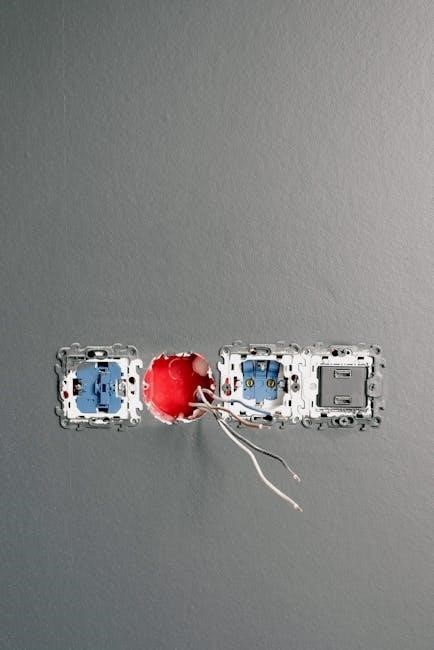
Identifying miswired circuits relies heavily on a detailed circuit breaker panel wiring diagram PDF. Carefully compare the physical wiring within the panel to the diagram’s representation. Look for discrepancies in wire colors – black wires should connect to breakers, white to the neutral bus, and green/bare to ground.
Incorrect connections can cause breakers to trip frequently, appliances to malfunction, or even pose a fire hazard. Pay close attention to wire numbering conventions detailed in the diagram. If a circuit isn’t functioning, trace the wiring path on the diagram to pinpoint potential errors. Remember safety first – always de-energize the circuit before inspecting wiring!
Recognizing Overloaded Circuits
A circuit breaker panel wiring diagram PDF is invaluable when recognizing overloaded circuits. The diagram reveals the total amperage capacity of each circuit based on the breaker size. Frequent tripping of a breaker signals a potential overload – too many devices drawing power simultaneously.
Consult the diagram to identify all devices connected to that circuit. Reduce the load by unplugging appliances or redistributing them across different circuits. Remember a 200A service with a 115A feeder limits capacity. Ignoring overloads can damage wiring and create fire risks. Always prioritize safety and consult a qualified electrician if issues persist.
Advanced Concepts
Circuit breaker panel wiring diagram PDFs reveal complex systems like DC control wiring, exemplified by Westinghouse DHP panels, illustrating voltage and current flow intricacies.
DC Control Wiring (Westinghouse DHP Example)
Circuit breaker panel wiring diagram PDFs, particularly those for Westinghouse DHP panels, showcase intricate DC control wiring. These diagrams illustrate how a low-voltage DC circuit operates the main breaker, enabling remote control and monitoring. The black wires, fed by separate breakers, and white wires connected to the transformer return are key elements.
Understanding this system requires deciphering the diagram’s components and their electrical sequence. The diagram details the interaction between relays, control circuits, and the main breaker itself. Analyzing a typical wiring diagram reveals how DC signals initiate breaker operations, offering insights into the panel’s sophisticated functionality and safety mechanisms.
Understanding Voltage and Current Flow
Circuit breaker panel wiring diagram PDFs visually represent the path of voltage and current throughout an electrical system. These diagrams demonstrate how power enters the panel, distributes to individual circuits via bus bars, and ultimately reaches appliances. Comprehending this flow is vital for safe troubleshooting and modifications.
The diagrams illustrate the relationship between hot (black), neutral (white), and ground (green/bare) wires. Voltage drives current, and the diagrams show how breakers interrupt this flow during overloads. Analyzing these diagrams clarifies how components interact, ensuring a stable and secure electrical supply, preventing potential hazards within the system.
Leave a Reply
You must be logged in to post a comment.